Casio CPS-85 User Manual Page 6
- Page / 24
- Table of contents
- BOOKMARKS
- ELECTRONIC KEYBOARD 1
- SPECIFICATIONS 2
- CONTENTS 2
- ELECTRICAL 3
- BLOCK DIAGRAM 4
- CIRCUIT DESCRIPTION 5
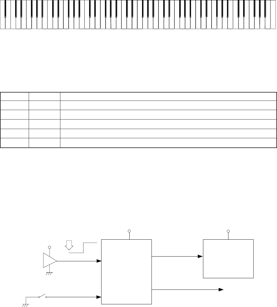
- NOMENCLATURE OF KEYS 6
- POWER SUPPLY CIRCUIT 6
- RESET CIRCUIT 6
- CPU (LSI4: GT913F) 7
- FILTER BLOCK 9
- DAC (IC1: UPD6379GR) 9
- MAJOR WAVEFORMS 11
- PRINTED CIRCUIT BOARDS 12
- SCHEMATIC DIAGRAMS 13
- Keyboard PCB JCM886T-KY1M 16
- Keyboard PCB JCM886T-KY2M 17
- Keyboard PCB JCM886T-KY3M 18
- EXPLODED VIEW 19
- PARTS LIST 21
- 8-11-10, Nishi-Shinjuku 24
- Shinjuku-ku, Tokyo 160, Japan 24
- Telephone: 03-3347-4926 24
Related products and manuals for Digital pianos Casio CPS-85
 (44 pages)
 (45 pages)
 (19 pages)
 (37 pages)
(21 pages)
(16 pages)
(56 pages)
(37 pages)
(20 pages)
(58 pages)
(54 pages)
(108 pages)
(220 pages)
(163 pages)
(168 pages)
(77 pages)
(49 pages)
(37 pages)
(21 pages)
(16 pages)
(56 pages)
(37 pages)
(20 pages)
(58 pages)
(54 pages)
(108 pages)
(220 pages)
(163 pages)
(168 pages)
(77 pages)
(49 pages)
© 2020, manymanuals.com. All rights reserved. | 0.320 s |
 Manymanuals.com
 Manymanuals.de
 Manymanuals.fr
 Manymanuals.it
 Manymanuals.pl
 Manymanuals.cz
 Manymanuals.es
 Manymanuals-pt.com
Comments to this Manuals